
Adjusting the pressure in a hydraulic circuit is not just about turning a screw on a relief valve. The reliability of the result depends on conditions that are rarely mentioned in standard procedures: fluid temperature, presence of air in the circuit, type of measuring instrument used. Without these precautions, the value read on the pressure gauge does not reflect the actual operating pressure.
Fluid Temperature and Air Bleeding: Two Prerequisites That Change the Measurement
The viscosity of a hydraulic fluid varies with its temperature. An adjustment made when cold gives a different pressure than that observed once the system is stabilized at its operating temperature. The discrepancy can be enough to distort the setting of a relief valve or pressure reducer.
Before any adjustment, the circuit must run long enough for the fluid to reach its normal thermal range. On an industrial hydraulic unit, this often takes several minutes of operation at no load.
The other underestimated factor is the presence of air pockets. Trapped air in a circuit compresses the liquid column unpredictably, causing pressure fluctuations on the gauge. The adjustment of hydraulic pressure can only be reliable after a methodical bleeding of each high point in the circuit. On some systems, bleed screws are provided for this purpose on cylinders and distributors.
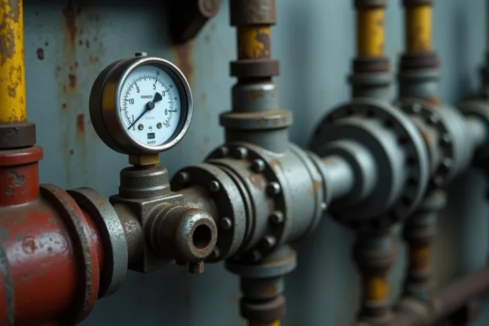
Analog or Digital Pressure Gauge: The Tool Determines the Adjustment Accuracy
Technical content often focuses on manipulating the valve, rarely on the quality of the measuring instrument. A low-end analog gauge, with poor precision class, introduces a margin of error that makes the adjustment approximate.
Recent professional guides recommend using digital gauges for pressure monitoring. Their finer resolution allows for detecting variations that the needle of an analog dial does not show. In a circuit where the operating pressure is only a few bars (as in domestic installations between 1.5 and 3 bars), this difference in precision matters.
The Measurement Point Is Not Trivial
A gauge placed at the pump outlet does not give the same reading as a gauge installed closest to the cylinder or the final tap. Pressure losses in the piping, bends, and fittings reduce the effective pressure. For a relevant adjustment, the measurement must be taken at the most representative point of the actual circuit usage.
Relief Valve and Pressure Reducer: Two Components, Two Adjustment Logics
Confusing these two components is a common mistake. The relief valve (or pressure limiter) protects the circuit against overpressure: it opens when the pressure exceeds a threshold, returning the liquid to the tank. The pressure reducer, on the other hand, maintains a stable pressure downstream, regardless of fluctuations upstream.
The relief valve is adjusted by gradually increasing the pressure to the desired value, then locking the locknut. The reducer is adjusted in the opposite direction: starting from a higher pressure and reducing it to the setpoint. Reversing the logic forces the component out of its operating range.
- Relief valve: loosen the locknut, screw in the adjustment screw to increase the opening threshold, check on the gauge, then lock the locknut.
- Pressure reducer: turn the screw in the decreasing direction until the target value is read downstream, stabilize, then lock.
- Pump pressure switch (booster): adjust the activation and deactivation thresholds by acting on the main spring and, if present, the differential spring.
On a domestic booster equipped with a pressure switch, adjusting the low threshold (activation pressure) and the high threshold (deactivation pressure) conditions the comfort at the tap and the longevity of the pump. A gap that is too small between the two thresholds causes short cycles that prematurely wear out the motor.

Traceability of Adjustments: A Still Marginal Practice on Small Circuits
In industrial installations, documenting pressure values before and after intervention is becoming a standard for preventive maintenance. Recording the initial pressure, target pressure, and measured pressure after adjustment allows for detecting a gradual drift of the system during subsequent interventions.
This approach remains little applied on domestic circuits or small mobile equipment. Field feedback varies on this point: some technicians consider traceability unnecessary for a simple circuit, while others find that it helps to identify a component nearing the end of its life (worn valve spring, worn pump seal) before a complete failure.
What Traceability Reveals About the Circuit’s Condition
A relief valve that requires increasingly tighter tightening to maintain the same pressure signals a weakened spring. A growing gap between the setpoint pressure and the actual pressure indicates internal wear of the pump or a leak in the circuit. Without a history of measurements, these signals go unnoticed until failure.
- Note the date, fluid temperature, measurement point, and the value read before each adjustment.
- Compare with previous readings to identify a downward trend or instability.
- Check the flow in parallel: correct pressure with falling flow often betrays a pump problem, not an adjustment issue.
Pressure alone is not sufficient to qualify the proper functioning of a hydraulic network. A low flow combined with normal pressure on the gauge can mask a partial obstruction of the piping or a clogged filter. Adjusting the pressure only makes sense in a circuit whose mechanical condition and sealing have been verified beforehand.